Circuit Analysis
– Week #5 Lab
Sinusoidal Steady State
Analysis
This week’s lab is based on the sinusoidal steady state analysis
using capacitive and inductive
circuits in Multisim.
1.
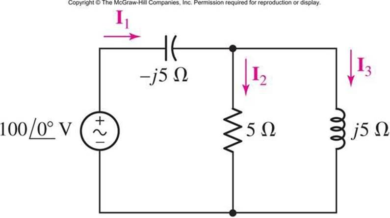
In the frequency
domain circuit below,
determine the currents
I1, I2 and I3. Make sure you show your work.
2.
Switch the places
of capacitor and inductor and repeat step 2 to determine the currents. Show your work.
3.
Record the values
in the table below for the magnitude
and phase angle of each current:
|
|
Current I1
|
Current I2
|
Current I3
|
|
|
Calculated
|
Measured
|
Calculated
|
Measured
|
Calculated
|
Measured
|
|
Step 2
|
|
|
|
|
|
|
|
Step 3 (Capacitor and Inductor Switched)
|
|
|
|
|
|
|
4. Using a frequency of 100 Hz, determine the value of the capacitor
and inductor to get the values of XC and XL in the schematic; make sure you show your work.
Construct the circuit above in Multisim using 100 Vrms with 100 Hz for the AC POWER source voltage (make sure you
double click on the AC POWER source and change the AC ANALYSIS MAGNITUDE
field to 100 also).
a.
Run the simulation to measure the currents I1, I2 and I3 using a DVM. (Use
5% tolerances for the resistor). Take screenshots of your
measurements.
b. Perform Single Frequency AC Analysis for the component
currents and display the
magnitude and phase angle for each component.
c. Calculate the average
power, reactive power and apparent
power supplied by the voltage
source.
d. Switch the capacitor and inductor and repeat the above measurements and power calculations.
e. Take the screen capture
of all the measurements and the Single
Frequency AC analysis.
5.
Answer the following
questions:
a. Are the measured values
the same as calculated values?
If not, explain why they are
different?
b. Compare the measurements of currents from step 2 and 3 and explain
the differences?
c. What do you understand from the Single Frequency AC analysis of this
circuit?
6. Create a new word document called
“Lab5_StudentID.docx” with your GID
substituted into the file name.
7. Save the analysis from step 2 & 3 and simulation results from step 5 along with the table and screen captures of all the
measurements. Make sure to answer the questions in step 5.
8.
Upload file “Lab5_StudentID”.
Rules for lab submissions:
1.
The lab document
must be a Word document. PDF files are NOT accepted.
2.
All screenshots must be included.
3.
All screenshots must include the Multisim time stamp.
4.
Any and all Multisim
files must be submitted.
5. Any equations used must be typed in Word. Copy and paste of equations from outside sources is prohibited.
6.
No graphics are allowed in the Word document other than screenshots of circuits from
Multisim with the time stamp.
7. The lab template should
be used. Specifically, it is brought to your attention
that a summary MUST be provided
explaining the results
of the labs, the relationship of the results to expected
results, and any challenges encountered.
8. All resistors in must be have a tolerance of at least
5% set. Thus, your measured values should NOT be
exactly equal to your calculated values.
Any violation of the submission rules above will result in a grade of 1.