Electronics II and Lab – Week 3 Lab
MOSFETs
INTRODUCTION
Discuss the basic
differences between JFETs and MOSFETs.
Why should MOSFETs
be handled with special care?
EQUIPMENT
·
1 power
supply: 15V
·
2
transistors: MTP8N50E , IRF510
·
1
resistor: 470Ω
·
1
potentiometer 500kΩ
·
1
diode: red LED
·
<List
meters used>
PROCEDURE
Using Multisim
construct the circuits shown below:
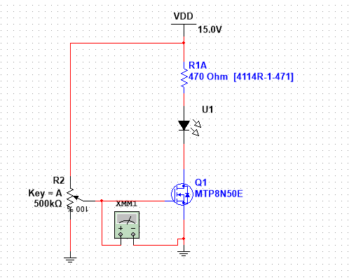
Set the
potentiometer to 0% then measure and record VGS, ID, VD.
Set the value to
45% and take the three measurements.
Increase the
potentiometer until the LED turns off, record the readings.
Replace the
transistor with the IRF510 and repeat steps a) through c).
RESULTS
|
|
MTP8N50E |
IRF510 |
||||
|
|
VGS |
VD |
ID |
VGS |
VD |
ID |
|
0% |
|
|
|
|
|
|
|
45% |
|
|
|
|
|
|
|
LED off |
|
|
|
|
|
|
Discuss the
results.
What types of
applications can this circuit be used in? Explain.
CONCLUSION
What did you learn?
Rules
for lab submissions:
·
The lab document must be a Word document. PDF files are NOT
accepted.
·
All screenshots must be included.
·
All Multisim screenshots must include the date/time stamp.
See TOOLS AND TEMPLATES for the procedure to display the date and time.
·
Any and all Multisim files must be submitted.
·
Any equations used must be typed in Word. Copy and paste of equations from outside sources is prohibited.
·
No graphics are allowed in the Word document other than
screenshots of circuits from Multisim and hardware if applicable, with the
date/time stamp.
·
The lab template should be used. Specifically, it is brought
to your attention that a summary MUST be provided explaining the results of the
labs, the relationship of the results to expected results, and any challenges
encountered.
·
Hardware portion of labs should include screenshots of the
assembled circuit with your name and student GID number written on paper next
to the circuit. There should be screenshots of the instrument
readings with the date and time stamp on lower right corner clearly shown. .
Any violation of
the submission rules above will result in a grade of 1.